 |
Specifications |

|
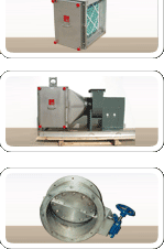
Housing General Specifications : 1. The filter housing shall be a bag in-bag out assembly allowing filter change without contact with the filter cartridge. Housing shall be fabricated from 14 gauge 304 stainless steel and reinforced to withstand a minimum pressure of 10” WG in accordance with ASME BPVC, Section IX. All internal parts shall be constructed of 300 Series stainless steel, except for brass travel nut in clamping mechanism. The housing shall accommodate standard gasket seal filters. 2. Positive seal clamping mechanisms shall exert a minimum of 1200 lbs force on each filter. This force shall be supplied by leaf springs, which insure a tight seal after gasket long-term relaxation. The clamping mechanism shall be operated outside the change-out bag. The access door shall extend over the clamping mechanism operators such that tampering with the clamping mechanism is not possible without door removal. Aluminum door knobs shall stay attached to door after removal to prevent loss. 3. The housing shall have a bagging ring around each filter access port. The bagging ring shall have two (2) continuous ribs to secure the PVC change-out bag. Access opening shall fully contain the change out bag within the housing when the door is secured. 4. The housing shall be manufactured under a quality assurance program that meets all the requirements of ASME NQA-1. Entire housing shall be factory leak tested at 10” WC in accordance with ASME-N510. Both the housing body and seal face will be tested using the pressure decay method. There shall be a maximum leak rate of 0.0005 CFM per cubic foot of housing volume at 10” WC. 5. A minimum of four (4) feet clearance in front of the filter access door is suggested for filter change out. 6. Multi-wide housings shall be equipped with a filter removal rod to draw the filters to the change out position. The removal rod shall be operated from within the change-out bag. 7. All pressure retaining weld joints and seams shall be continuously welded with no pores allowed. All weld seams shall be chemically cleaned to remove all heat discoloration. All welding procedures and welders shall be qualified in accordance with ASME Boiler and Pressure Vessel Code, Section IX. Welds on flanges shall be ground smooth. 8. The upstream and downstream flanges shall have a 1 ½” inch minimum flange width. 9. One PVC change out bag shall be furnished for each filter access port. Each amber matted bag shall be 8 mil thick with two gloves. An elastic cord shall be hemmed into the mouth of the bag so that it fits securely when stretched around the bagging ring. To prevent the bag from sliding off the bagging ring during the change-out process, a nylon security strap shall be provided with each filter access port. 10. Static pressure taps shall be ¼” IPS pipe half coupling. ADDERS: 1. Removable change-out tray shall be provided to support filter during change-out procedure. The tray shall be fastened to housing after removal of door. 2. Provide DOP test ports in accordance with ANSI N510 manufacturer’s recommendation. 3. Provide factory mounted Dwyer magnahelic gages across each filter access port. Damper General Specifications CCD style round bubble – tight dampers The CCD style damper shall be a positive seal, isolation type damper which shall be bubble tight at a differential pressure of 10” water gage. Damper shall be constructed with a 10 Ga. T-304 stainless steel body and 3/16” thick flanges. The blade shall consist of two 3/16” thick disks with a replaceable neoprene or silicone gasket between them. The shaft shall be sealed with two replaceable polypak gland seals. The damper interior shall be continuously seam welded. All welds shall be chemically cleaned to remove heat discoloration. The dampers shall be manufactured under a quality assurance program that meets all the requirements of ASME NQA-1. All welds and welders shall be qualified in accordance with ASME Boiler and Pressure Vessel Code Section IX. The damper blade and shaft seals shall be tested at 10” water gage and tested in accordance with ASME N509-1996 class I. The complete pressure boundary shall be leak tested by the “Pressure Decay Method” in accordance with ASME N510-1995 “reaffirmed”, “Testing of Nuclear Air Treatment Systems”, Paragraphs 6 and 7. There shall be a maximum leak rate of 0.0005 CFM per cubic foot of housing volume at 10 inches water gage. |
© 2007 Contamination Technology Corporation All rights reserved |
|
|||||
